
No products in the cart.

How to Control a DC Motor with H-Bridge and Arduino and IR sensor
A motor is a device that converts electrical energy into mechanical energy. It is arguably the most important component in a robot because it is responsible for all the structural movements. In robotics, DC motor, stepper motor, and servo motor are the three common types of motors. Each is ideal for a particular application. In this project, the focus will be on the use and control of a DC motor.
A DC motor is the simplest of the three aforementioned types of motors. It consists of two terminals. These terminals must be connected to a DC source such as a battery. Depending on the polarity of one terminal with respect to the other, the motor either spins clockwise or anticlockwise. Thus, you can manually change the direction of rotation of a motor by reversing the polarities. Alternatively, you can utilize an H-Bridge circuit or IC to automatically control the direction of spin. In this project, we shall learn how to use the latter method to control the direction of spin of a DC motor in our Arduino project. Precisely, we shall use the SN754410 Quad Half H-Bridge motor driver IC.
How SN754410 H-Bridge Motor Driver Works
The SN754410 Quad Half H-bridge is a handy, cheap, and fast motor driver that allows you to control the speed and direction of a DC motor. It is capable of driving a high voltage motor of 4.5V – 36V and constant 1A using TTL 5V logic levels. This H-bridge is designed for positive-supply applications only and can drive up to two motors. With an Arduino board, the SN754410 bridge only needs three inputs from the board. The first one is a speed control input and the other two are digital inputs for controlling the spin direction. Therefore, on the Arduino board, you will need to reserve at least three digital output pins; one as a PWM and the other two as digital outputs. In this project, we shall use

Circuit Design
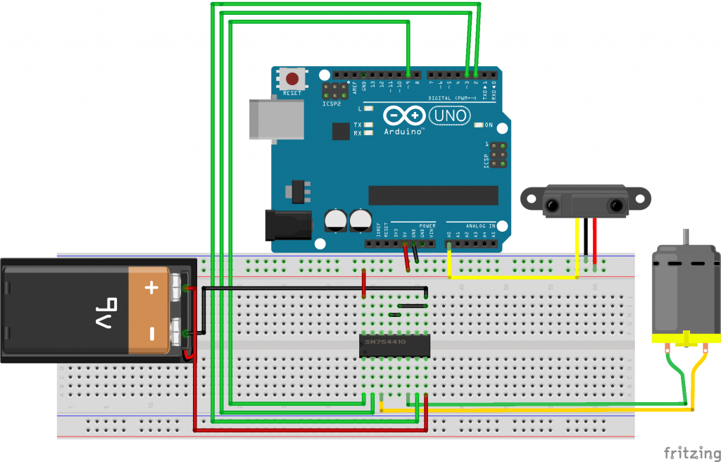
Arduino Sketch
const int EN=9; //Half Bridge 1 Enable
const int MC_1=3; //Motor Control 1
const int MC_2=2; //Motor Control 2
const int IR_sensor=0; //IR_sensor on Analog Pin 0
int val = 0; //for storing the reading from the IR_sensor
int velocity = 0; //For storing the desired velocity (from 0-255)
void setup()
{
  pinMode(EN, OUTPUT);
  pinMode(MC_1, OUTPUT);
  pinMode(MC_2, OUTPUT);

  brake(); //Initialize with motor stopped
  Serial.begin(9600);
}
void loop()
{
  val = analogRead(IR_sensor);
  Serial.println(val);
  delay(500);
  //go forward
  if (val > 200 )
  {
    for(int i = 0; i<256;i++){
      forward(i);
      Serial.println("forward");
      delay(20);
      }
      brake();
      delay(2000);
      for(int i = 256; i >0;i--){
        reverse(i);
        delay(20);
        Serial.println("reverse");
        }
      }
      brake();
     }
//Motor goes forward at given rate (from 0-255)
void forward (int rate)
{
  digitalWrite(EN, LOW);
  digitalWrite(MC_1,HIGH);
  digitalWrite(MC_2, LOW);
  analogWrite(EN, rate);
}
//Motor goes backward at given rate (from 0-255)
void reverse (int rate)
{
  digitalWrite(EN, LOW);
  digitalWrite(MC_1, LOW);
  digitalWrite(MC_2, HIGH);
  analogWrite(EN, rate);
}
//Stops motor
void brake ()
{
  digitalWrite(EN, LOW);
  digitalWrite(MC_1, LOW);
  digitalWrite(MC_2, LOW);
  digitalWrite(EN, HIGH);
}
Video Demo of DC Motor and H-Bridge Arduino Project
Julioceaseless
Julioceaseless is an electrical and electronics engineer, a DIYer, and a tinkerer who also loves to dabble in code. On this website, he builds and shares tutorials for DIY projects he has completed. He also sells DIY components to local customers.
William Jiménez
December 14, 2019Greetings Julioceaseless, excellent your video I am working on a vending machine project, with two nema 17 engines and I want to position them by taking the distance from the axis (x-y) with the IR sensor to control their location. Can you help me in this regard, I appreciate your valuable collaboration.
Cordially,
William J.
South America
Julioceaseless
Post author December 31, 2019Hello William,
Thank you for your kind comment. To respond to your query, the nema 17 is a stepper motor. As such, it needs to be connected to the two bridges of the SN754410 H-bridge. The red and yellow should be connected to one side while gray and green should be connected to the bridge on the other side. I will be posting a video of the same soon. You can subscribe to my youtube channel to stay on the loop.
SELCO USA
April 7, 2022That’s really informative thankyou for sharing.
If you are looking for a ground fault monitoring system, contact Selco USA, Inc. They offer the best ground fault monitoring system, which can monitor deteriorations of the insulation level & monitor high resistance grounding effectively at an early stage.